How it works
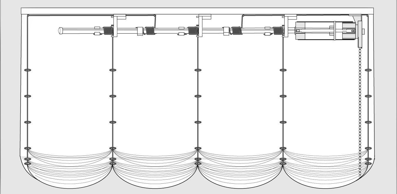
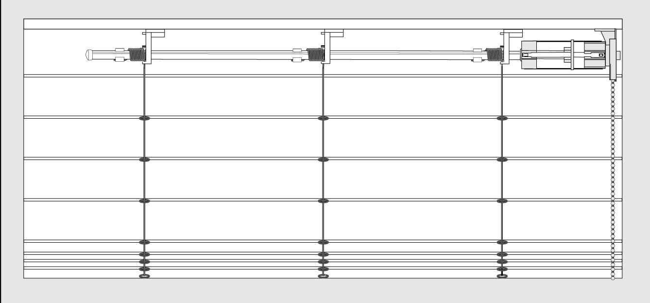
One lowers and raises the blind by pulling on the control cord. This releases the clutch allowing easy repositioning of the blind. When one stops pulling down on the control cord, the clutch automatically holds the shade securely in position. The RollEase system keeps shade hanging level by wrapping individual lift cords around a rotating and traversing shaft.

Specifications
Maximum blind weight: 13.5kgs (54mm Clutch), 6.5Kgs (38mm Clutch) including fabric, rings, trim, stiffeners and bottom weight, but not including the headboard or RollEase components.
Maximum blind drop: 3.6metres when using the recommended 0.9mm lift cord.
Maximum blind width: Unlimited – provided blind is 13.5kgs or less.
For best results: Follow the instructions carefully.
Note: The RollEase system brackets and clutches are available in two widths – 54mm or 38mm – All other components can be used with either size clutch. Note: The Blinds in this booklet are shown using the 54mm parts. The same instructions apply to the 38mm system.
Blind Options
You can make blinds with or without edge lifts and with as few as two Shaft Brackets. In determining the number of lift lines and thus the number of brackets, the general rule is that each lift can be lifting no more than 3.35kgs. Per lift line. For example: a 9kgs blind would require an absolute minimum of 4 lift lines. (2.25kgs max per lift line). Having more lift lines than the absolute minimum is preferred.
With "Edge Lifts"
Edge lifts are routed through screw eyes and then guided to the shaft through Shaft Brackets or screw eyes. Edge lifts must be 5mm to 30mm from both edges of the blind and be routed to an interior Shaft Bracket via a screw eye. Brackets must be at least 175mm or more from either edge of the blind for all blind scenarios. For most blinds with a 2400mm or less drop; 175mm or more is sufficient space between brackets. For blinds with greater than 2400mm drop lengths, the distances between brackets needs to be increased. The drop length of your blind determines how much space between brackets is required. Use this guideline chart to determine the absolute minimum interior Shaft Bracket spacing for a blind with edge lifts.

Without “Edge Lifts”
Shaft Brackets should be placed 175mm or more from either edge of the blind. Interior Shaft Brackets can be placed closer together if necessary.
For most blinds, interior Shaft Brackets are 175mm or more apart, but for extreme and rare situations use this guideline chart to determine the absolute minimum interior Shaft Bracket spacing for a blind without edge lifts, given the drop length.

Overview
Items shown are not to scale.
HEADBOARDS: made of a piece of 40 x 18mm or 55 x 18mm pine.
It may be wrapped with cloth or left bare.
SCREW EYES: used as lift cord guides for edge lifts.
2 DISK SCREWS are used to secure the drive disk to the shaft.
The MOUNTING SCREWS (pozi screws) are used to fasten the
Clutch and Shaft Brackets to the headboard.
“J” BRACKETS: used to mount headboard to window or wall.
All blinds must be hung with the brackets in traditional top fix way.
(Brackets cannot be hung in the traditional face fix way.)
SHAFT: 9.5mm aluminum rod with 3 grooves along the length.
END CAP: used to cover the exposed end of the shaft.
SHAFT JOINER: use two joiners to splice together two
pieces of shaft.
SPEARS: transmit clutch torque to the shaft via the drive disk.
DRIVE DISK: fastens to the shaft with two drive disk screws
and is guided by the spears.
SPEAR RETAINER: used to hold and protect the ends
of the spears.
CLUTCH: the mechanism that raises and lowers the blind by
means of a control cord or bead chain.
SHAFT BRACKETS: support the shaft and guide the lift cord to
uniformly wind onto the shaft.
CORD CLIPS: designed to clip onto the shaft and used to hold the
knotted end of the 1mm LIFT CORD.
BOTTOM RINGS (OPTIONAL): used as the bottom row of rings
on the BLIND. Used in conjunction with the BOTTOM RING
PLUGS, which allow you to easily adjust and equalize tension
on all lift cords.
CONTROL CORD: threaded into the clutch and used to raise and
lower the blind. It may be a polyester cord, nylon bead chain or
stainless steel bead chain. (chain is required for blinds over 4.5kgs).

Tools
Assembly tools:
To assemble the RollEase Soft Blind System, you will need a PHILLIPS HEAD SCREWDRIVER, NO.2 POZI HEAD SCREWDRIVER, AWL, PLIERS, FILE, SCISSORS, TAPE MEASURE, PENCIL and HACK SAW or POWER MITRE SAW.
Preparation
It is important that bracket spacing and positioning be calculated before you attach lift rings to your blind so that your shade and the lift system will align properly. Minimum Shaft Bracket positioning and spacing varies depending on the drop length of your blind. (see the guidelines above). If you are using edge lifts, make sure the column of rings are sewn between 5mm and 30mm from the edges of the fabric. Construct the blind so when stacked the topmost rings are at least 90mm or more below the top of the headboard. Use RollEase BOTTOM RINGS (OPTIONAL) for bottom row as shown in the diagram below.
Mark and cut headboard to width of blind, You may either paint headboard, leave it bare, or wrap with chosen fabric. Staples may be used to secure fabric to wood.
Lay headboard on the work table in front of you (stapled side down if covered).

Assembly
Instructions shown are for right hand clutch with Edge Lifts
Line up and attach blind to headboard
If edge lifts are used, attach SCREW EYES to each end of the HEADBOARD centered on the headboard so that the screw eyes are
in line with edge rings on the blind. The edge rings on any blind must be between 5mm and 30mm from the edge of the fabric.
Edge lifts are optional and depend on the design and construction of blind. See above for diagram of a blind with and without edge lifts. Skip edge lift instructions if they do not apply. All other instructions remain the same.
Cut SHAFT 150mm shorter than headboard. Cut must be made square. File off rough edges.

Attach DRIVE DISK firmly and squarely to the shaft.
Use two DISK SCREWS to secure Drive Disk. Make sure disk is seated squarely. Screw must be flush.
Slide SPEAR RETAINER onto the other end of the shaft as shown.
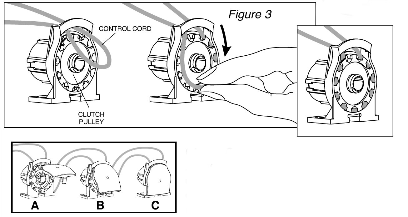
Insert CONTROL CORD into the CLUTCH by slipping a loop through the opening of the clutch as shown in figure 3. While holding right side of the control cord between your thumb and forefinger, press fingers lightly against the clutch pulley and turn one revolution clockwise, as if dialing a rotary telephone, until cord is completely inserted into clutch. For shades over 4.5kgs, metal bead chain is required and installs the same as control cord.
Slide one end of a SPEAR into the grooves on the CLUTCH making sure the Hole on the spear securely snaps and locks onto the locking barb in the clutch. Once the spear is inserted, it can’t be removed. If using only two spears (blind weight under 4.5kgs), install them on opposite sides of the clutch.

Use 2 spears for shades under 4.5kgs.
Use 4 spears for shades over 4.5kgs.
Short Spear
Use on shades up to 2700mm Drop
Long Spear
Use on shades up to 3700mm Drop
Slide Drive Disk onto the spears. Insert and lock the Spears into the Spear Ports on the Spear Retainer. Important: if using only two spears on the Clutch you must make sure that these two spears mate with the two Spear Ports that have the locking barbs.


Slide one BRACKET for each lift cord (including edge lifts, if any) onto shaft with “feet” (see Figure 6) pointing towards the clutch and add shaft End Cap. Note: For this example: brackets #2 & #3 will be used for edge lifts. Screw eyes may be substituted for “edge lift” brackets #2 & #3, unless these represent the only two lift lines on the blind. (A minimum of 2 brackets must be used. Remember: 2.25kgs Maximum per lift line)
Position CLUTCH ASSEMBLY on headboard 5mm to 10mm from screw eye. If no edge lifts are used, position 10mm from edge of headboard. Make sure the feet of clutch are straight and the shaft lines up with center of headboard. Screw clutch onto headboard but do not tighten.
Beginning with BRACKET #1 (Closest to the CLUTCH), align lift cord guides on bracket (figure 7A) with center of corresponding column of lift rings on the blind. Make sure shaft moves freely. Remember most blinds with a 2400mm or less drop, 175mm or more is sufficient space between each interior Shaft Bracket. For blinds with a greater than 2400mm drop length, the space between Shaft Brackets needs to be increased ( see edge lift chart, page 3). Mark the bracket positions and screw lightly onto headboard. Repeat for all remaining brackets in order shown (Brackets #1 first, then #2, #3 and #4). Test shaft movement after tightening each bracket. Tighten all screws on brackets and clutch.
Check shaft alignment again after brackets have been tightened. If shaft does not slide freely when all brackets are installed, check bracket alignment and adjust. Make sure all screws are tight before proceeding to step 8.

Measuring the lift cords:
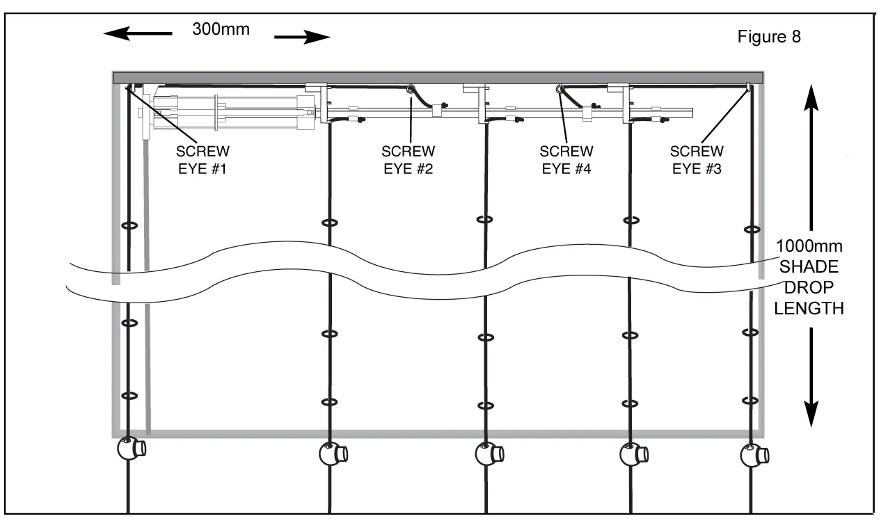
- For edge lift measurement, measure the distance from Screw Eye #1 to edge lift Bracket #3. Add this distance to the length of shade and then add another 250mm. For example: A 1000mm blind length + 300mm between screw eye #1 and bracket #3 = 1300mm + an additional 250mm = 1550mm of lift cord. Do the same for screw eye #2 and bracket #2.
- For inner lift measurements, measure length of blind and add 250mm For example: A 1000mm blind length + 250mm = 1250mm lift cord.
Attaching Edge Lift Cords
- The shaft must remain against the clutch for the remaining operation. If edge lifts are not used, go on to step 9E.
- Feed one edge lift cord through the screw eye #1, beside (if using clutch covers) or under the clutch (between the feet of the clutch) and under brackets #1 and #3 and up to the shaft through the cord guides on bracket #3 as shown in figure 9A. Tie a knot at the end to prevent the cord from pulling back through the cord guides. Feed the other edge lift cord through screw eye #2 and through cord guides on bracket #2 (figure 9B). Tie a knot at the end.
- Align shaft correctly before attaching cord clips. With aluminum shaft, the groove should point down. Insert knot into cord slot of a CORD CLIP. (Figure 9C below ) Position cord clip 10mm away from the bracket with the tail of the knot facing away from Clutch. Insert key of cord clip into one groove of shaft. Snap on as shown in Figure 9D. Repeat for second edge lift making sure both cord clips are in the same groove. If necessary, rotate shaft so knots in cord clips face down & cord is not wrapped on shaft.

Attaching Inner Lift Cords
Thread inner LIFT CORD through SHAFT BRACKET CORD GUIDE and tie a knot on the end. Make sure shaft is against clutch. Insert knot into cord slot of a CORD CLIP and fasten to shaft 5mm from bracket with knot end away from clutch. Insert key of clip into top groove of shaft. Repeat for each bracket.
Note: All inner lift cord clips should be placed in the same groove the same distance from each bracket. Make sure no cord is wrapped around the shaft.

Securing lift cords:
This is best done with blind in hanging position or whole blind on a flat surface with headboard clamped to surface.
If using bottom Ring Set thread the LIFT CORD down through the small hole in the BOTTOM RING and continue through the hole in the plug (tab on plug faces down). Loop it once more through the hole in the plug.
Repeat for each lift cord.
While holding the lift cord taut, slide the plug along the cord until the plug is pressed completely into the bottom ring.
Note: The cord tension may be adjusted by pulling the bottom plug out of the bottom ring and sliding the plug up or down until tension is correct. Insert the plug back into the bottom ring when tension is correct. Repeat for each lift cord until they are all even and there is no slack. IMPORTANT: Tension must be equal on all cords.
If using plain rings. While holding the lift cord taut, tie a secure knot. Repeat for each lift cord until they are all even and there is no slack. IMPORTANT: Tension must be equal on all cords.
Once the shade is complete, run it up and down several times, check the tension on the lift cords and cut off the excess lift cord and remove the bottom ring plug tabs.
Shade is complete and ready to be hung